Listed as Free on Udemy when checked on 7 November 2026. No coupon or subscription trial is required for the listed lessons. Enrollment needs a Udemy account; availability can change.
About this course
Hardware can behave correctly on a workbench and still interact poorly with nearby electronics. Electromagnetic compatibility, or EMC, asks designers to consider those interactions as part of the product rather than as an afterthought. This free EMC engineering course offers a practical introduction to recognizing interference risks in familiar objects: cables, circuit boards, enclosures and switching circuits.
Karen Burnham teaches the English-language course for people involved in hardware development. It is classified as intermediate and assumes basic electromagnetic-field knowledge, Ohm’s law, and familiarity with resistors, capacitors and inductors. The single section contains seven videos totaling 98 minutes and 49 seconds. Electrical, mechanical and aerospace engineers, technicians and technical managers are among the intended learners.
| Official course | EMC Engineering Basics |
|---|---|
| Created by | Karen Burnham |
| Platform | Udemy |
| Language | English |
| Level | Intermediate |
| Listed duration | 98 minutes; 7 lectures across 1 section |
| Completion terms | Not included with a new free enrollment |
What you’ll learn
Explore how unintended antenna behavior can arise in cables, conductive loops and openings in enclosures. Connect switching waveforms with frequency-domain harmonics, and follow the purpose of a demonstration using a function generator, current probe and spectrum analyzer. Develop questions to bring into a design review before treating a product as ready for EMC testing.
Skills you’ll gain
- EMC concept interpretation
- Cable radiation awareness
- PCB loop analysis
- Enclosure aperture awareness
- Switching-noise reasoning
- EMI design-review planning
Look beyond the schematic
Begin by separating two questions. What electromagnetic energy might the equipment release into its surroundings? How might it respond to disturbances arriving from elsewhere? These correspond to emissions and immunity. Understanding one does not automatically establish the other. A useful review keeps track of both the possible source of a disturbance and the parts of the system that might respond to it.
The course introduces unintended antennas through cables, PCB traces and enclosure slots. A connection that looks like a simple wire on a schematic also has a physical route, nearby conductors and a return path. A metal housing likewise has joints and openings. These details help explain why electrical and mechanical decisions belong in the same conversation when investigating interference.
Connect switching behavior with a spectrum
The switching-noise lesson links time-domain waveforms with high-frequency content. A nominal switching frequency is only part of the picture: transition shape also matters. Texas Instruments’ application report on a particular boost converter illustrates how rise and fall times affect harmonic content. The general study lesson is to ask about waveform edges and current paths, while keeping the report’s component choices and measured results tied to that example.
This distinction prevents an easy mistake: copying a successful change from one board and assuming it guarantees the same outcome elsewhere. Layout, cable configuration, operating conditions and the way a measurement is made all influence what is observed. Record the conditions surrounding a result so that later comparisons have a clear basis. A single lower spectral peak is an observation to investigate, not a complete statement about product compliance.
Use observations to ask better questions
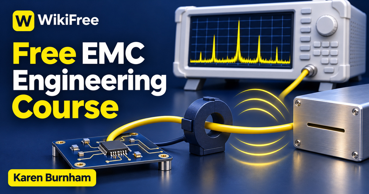
The listed hardware demonstration brings together a function generator, a current probe and a spectrum analyzer to illustrate cable behavior and differences between waveforms. As you study it, identify what supplies the signal, what senses the current and what displays frequency content. Keeping those roles separate makes it easier to understand what a measurement can show and what further information would still be needed.
The final lecture draws attention to design warning signs. Use that as a prompt for a structured discussion rather than a universal checklist of fixes. For each suspected issue, describe the feature you noticed, the mechanism you think may connect it to interference, and the evidence needed to evaluate that explanation. This keeps an early concern distinguishable from a demonstrated failure and a proposed remedy distinguishable from a validated improvement.
Turn the introduction into a review habit
For an editorial study exercise, sketch a fictional low-voltage device with a circuit board, external cable and enclosure. Mark possible noise sources and physical routes, then write three questions for its designer. Add a separate column for observations that would support or challenge each idea. The exercise requires no powered experiment and does not claim that a product has been built, tested or approved.
The course listing was last updated in January 2025. It is a starting point for understanding EMC, not a replacement for product-specific requirements, measurement planning or qualified engineering review. Six supporting resources are listed separately; no extra contents or laboratory access are promised here. Watching the recorded lessons is free. Test equipment, external laboratory services and any optional hardware costs are separate, and completing the introduction does not certify a product or guarantee that it will pass testing.
Read a TI example of radiated-EMI reduction: A component-specific application report, not a universal design approval.
Related courses for your next step
- Continue with circuit-design reasoningFree VHDL Digital Circuits Course
Explore gates, adders, sequential logic and state-machine examples.
Intermediate
- Connect schematics with board layoutFree KiCad Schematic and PCB Course
Follow a separate introduction to schematic capture and PCB work.
See course details
Frequently asked questions
What background is expected?
Basic electromagnetic fields, Ohm’s law, and familiarity with resistors, capacitors and inductors. The listing classifies the course as intermediate.
Do I need to own measurement equipment to watch?
The recorded demonstration uses a function generator, current probe and spectrum analyzer. The free lessons do not promise to supply that equipment or an external laboratory.
Does completing this course prove a product meets EMC requirements?
No. It introduces interference risks and design questions. Product requirements, testing and any necessary conformity assessment remain separate.
Questions & discussion
Share a useful question or correction. Comments appear after moderation. Please avoid personal or sensitive information.