Listed as Free on Udemy when checked on 9 November 2026. No coupon or subscription trial is required for the listed lessons. Enrollment needs a Udemy account; availability can change.
About this course
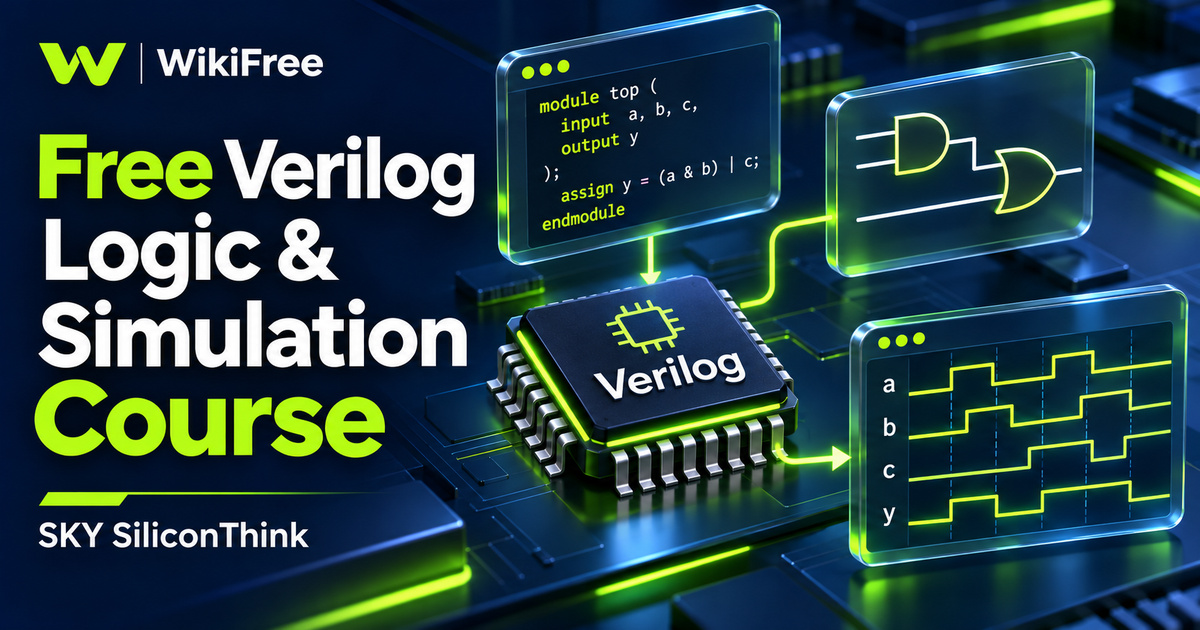
A few lines of hardware description can be difficult to understand until you connect them with a circuit and its changing signals. This free Verilog course offers a focused way into that relationship. Its central learning opportunity is to move between a small digital design, the code describing it and the waveform produced by a simulation, asking whether those views tell the same story.
SKY SiliconThink presents this English-language section of a larger VLSI and FPGA series. The listed course has one section and six lectures, totaling about one hour and 41 minutes; the final lecture is a short promotion for a separate DMA-controller project. The educational sequence concentrates on an introductory Verilog example, combinational logic, synchronous and asynchronous D flip-flops, and differences in simulated startup values.
| Official course | VLSI/FPGA Design P2-S2: Verilog for Design and Verification |
|---|---|
| Created by | SKY SiliconThink |
| Platform | Udemy |
| Language | English |
| Level | Beginner |
| Listed duration | 101 minutes; 6 lectures across 1 section |
| Completion terms | Not included with a new free enrollment |
What you’ll learn
Explore the roles of RTL and a testbench, follow a small Verilog simulation, and relate basic combinational logic to its description in code. Compare flip-flop reset behavior and inspect signal changes in waveforms. Recognize that simulator initialization settings affect what appears at the start of a run, so a clean-looking trace needs interpretation.
Skills you’ll gain
- RTL and circuit interpretation
- Testbench structure awareness
- Combinational logic reasoning
- Flip-flop reset comparison
- Waveform reading
- Simulator initialization awareness
Start with a small, understandable simulation
The Hello World lesson provides an entry point to Verilog and the distinction between describing hardware and supplying simulation behavior around it. That separation matters when reading examples: a statement used to observe or stimulate a design does not automatically become a component in a synthesized circuit. Treat the early example as a chance to identify the design under test, its surrounding testbench and the output used to inspect behavior.
The longest lesson develops combinational logic and simulation. Its public overview introduces modules, wire and reg declarations, continuous and procedural assignments, and testbench instantiation. Verilator and GTKWave form the named simulation and waveform workflow. As you follow it, keep a small table of inputs and expected outputs beside the code. This makes it easier to notice a mismatch than relying only on whether a tool finished without an error.
Give clocked behavior its own questions
The next substantial lesson compares D flip-flops with synchronous and asynchronous resets. It brings clock edges, reset sensitivity, assignments and waveform inspection into the same example. A useful study question is when the output is expected to change: at a relevant clock edge, in response to reset, or following a different condition in the design. Write that expectation before examining the trace.
This comparison is a starting point for reasoning about state, not a complete reset architecture guide. The course section does not establish that a design satisfies a particular FPGA's timing requirements, clock-domain constraints or implementation rules. Keep functional simulation separate from the later work of selecting a target device, synthesizing the design, checking timing and testing physical hardware.
Interpret startup values carefully
A short lesson highlights power-up simulation differences between Verilator and other tools. Current Verilator documentation describes it as mostly a two-state simulator and explains that initialization and explicit unknown-value handling depend on options. A displayed zero or one at startup therefore does not, by itself, prove that the intended reset behavior is correct. Check the simulation configuration and consider what the test actually exercised before drawing a conclusion from its first waveform values.
For an independent exercise, sketch a two-input combinational function and list its four possible input combinations. Then draw a separate clock-and-reset timeline for a one-bit storage element, marking when you expect its output to respond. These are original study prompts for comparing representations, not supplied course assignments or tested reference designs. They keep the practice small enough that you can explain each expected transition.
Know where this section ends
The wider description mentions FSMs, FIFOs, buses, SHA-256 and larger projects. Those ambitions describe the broader series, not a promise that this six-lecture section teaches all of them. The final promotional item should not be counted as a complete DMA, APB or AXI implementation course. Basic digital-logic knowledge and some C or C++ familiarity are requested, and the creator recommends subtitles to support understanding. Free access to this section does not include a guarantee of a qualification, professional readiness or access to every related course.
Check simulator initialization behavior: Official Verilator guidance on unknown states and initialization.
Related courses for your next step
- Compare another hardware description languageFree VHDL Digital Circuits Course
Explore gates, adders and state machines using VHDL and Quartus.
Intermediate
- Extend your verification studiesFree SystemVerilog SOC Verification Course
Explore a broader introduction to testbench organization and verification.
Intermediate
Frequently asked questions
Is this the complete VLSI and FPGA series?
No. It is chapter 2, section 2, with a focused sequence on basic Verilog logic and simulation. Other chapters and the promoted project are separate.
Do I need prior programming knowledge?
The listed prerequisites are basic digital fundamentals and basic C or C++ programming. The examples introduce Verilog within that context.
Does a successful simulation prove the hardware is ready?
No. Simulation checks the behavior exercised by a model and testbench. Target-device implementation, timing checks and physical validation are separate work.
Questions & discussion
Share a useful question or correction. Comments appear after moderation. Please avoid personal or sensitive information.